


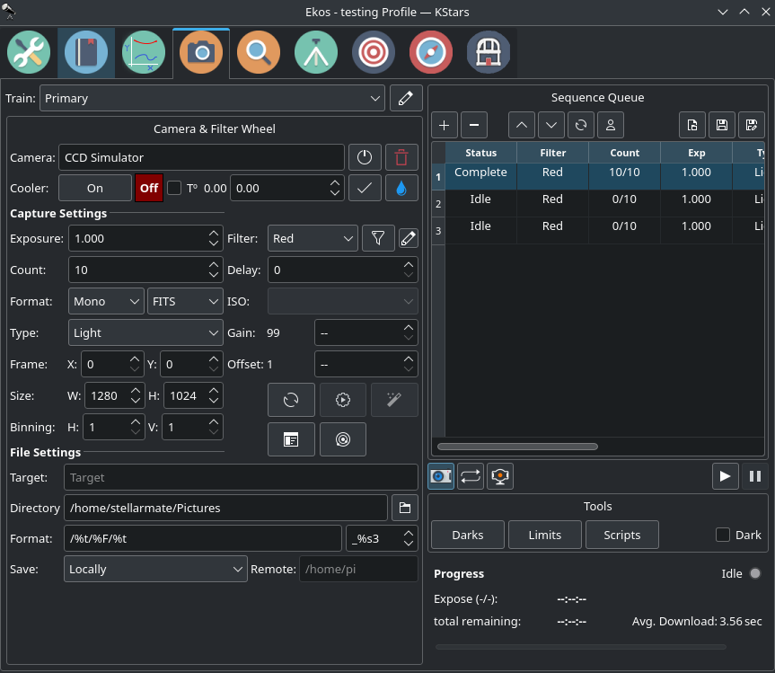
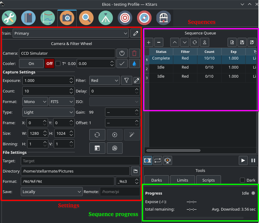
The Camera Module is your primary image and video acquisition module in Ekos. It enables you to capture single (Preview), multiple images (Sequence Queue), or record SER videos along with selection of filter wheel and rotator, if available. Capture settings on the left are grouped togeather and stored as a Sequence Job. You add each job to the Sequence Queue on right side.
After you added the desired Jobs, you can click on the Start (play button) to initiate the capture process.
Train
Each module has it's own train. You can use a specific train for Capture module. Click here to know more about Optical trains.
Camera & Filter Wheel Group
- Camera: Camera selection is according to the selected Train.
- Restart Camera Driver
 : Restarts the INDI driver for the active camera.
 - Clear Camera Configuration
 : Resets the INDI driver camera configuration back to default.
- Restart Camera Driver
- Filter Settings: Use the Filter Manager to specify various settings for each filter including exposure, offset, autofocus, and locking policy.
- Cooler: Toggle Cooler On/Off. Set the desired temperature, if you camera is equipped with a cooler. Check the option to force temperature setting before any capture. Capture process is only started after measured temperature is within requested temperature tolerance. The default tolerance is 0.5 degrees Celsius, but can be adjusted in Capture options under Ekos configuration.
Capture Settings
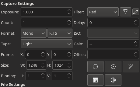 Set all capture parameters as detailed below. Once set, you can capture a preview by click on Preview or add a job to the sequence queue.
- Exposure: Specify exposure duration in seconds.
- Filter: Specify desired filter.
- Count: Number of images to capture
- Delay: Delay in seconds between image captures.
- Format: Specify capture save format. For all CCDs, only FITS option is available. For DSLR cameras, you can an additional option to save in Native format (e.g. RAW or JPEG).
- ISO: For DSLR cameras, specify the ISO value.
- Type: Specify the type of desired camera frame. Options are Light, Dark, Bias, and Flat frames.
- Gain: Specify the value of gain. Leaving it to -- would not change the current gain set in the camera.
- Offset: Specify the value added to avoid the reads to clip at value "zero". Leaving it to -- would not change the current offset set in the camera.
- Custom Properties: Set extended properties available in the INDI camera driver to the job settings.
- Calibration
 : For Dark & Flat frames, you can set additional options explained in the Calibration Frames section below.
 - Rotator Control
 : Opens the Rotator Settings dialog.
 - Dark Flat
 : Generate Dark Flat jobs to match the same exposure taken by the corresponding Flat frames. You need to add flat frames first, then generate dark flats afterwards.
 - Frame: Specify the left (X) and top (Y) offset in the frame in pixels. You can reset it to default values by clicking on the reset button.
- Size: Specify the resolution of the image taken by the Camera. You can reset it to default values by clicking on the reset button.
- Binning: Specify horizontal (X) and vertical (Y) binning.
Custom Properties
Many cameras offer additional properties that cannot be directly set in the capture settings using the common control. The capture controls described above represent the most common settings shared among different cameras, but each camera is unique and may offer its own extended properties. While you can use INDI Control Panel to set any property in the driver; it is important to be able to set such property for each job in the sequence. When you click Custom Properties, a dialog is shown divided into Available Properties and Job Properties. When you move an Available Properties to the Job Property list, its current value can be recorded once you click Apply. When you add a job to the Sequence Queue, the properties values selected in the Job Properties list shall be recorded and saved.
The following video explains this concept is more detail with a live example:
File Settings

Settings for specifying where captured images are saved to, and how to generate unique file names in addition to upload mode settings.
- Target: Name of the target.
- Directory: Local directory to save the sequence images to.
- Format: Format is used to define the image file names by the use of placeholder tags
- Placeholders:
- %f (filename): The name of the .esq file, without extension.
- %D (date/time): The current time and date when file is saved.
- %T (type): The frame type e.g: "Light", "Dark" etc
- %e (exposure): The exposure duration in seconds.
- %F (filter): The active filter name.
- %s (sequence): The image sequence identifier where * is the number of digits used (1-9). This tag is mandatory and must be the last element in the format.
- %t (target): The Target name.
- Suffix: Number of digits used to append the sequence number to the filename.
- Placeholders:
- Save: Select how captured images are uploaded:
- Locally: Captured images are saved locally on disk in the directory specified in the Directory field.
- Remotely: When connecting to a remote device, select this option to save images on the remote device only. No images are uploaded to Ekos.
- Both: Captured images are saved on both the remote computer and on the local disk as well.
- When selecting Remotely or Both, you must specify the remote directory where the remote images are saved to. By default, all captured images are uploaded to Ekos.
- Remote: When selecting either Remotely or Both modes above, you must specify the remote directory where remote images are saved to.
Limit Settings
Limit settings are applicable to all the images in the sequence queue. When a limit is exceeded, Ekos shall command the appropiate action to remedy the situation as explained below.
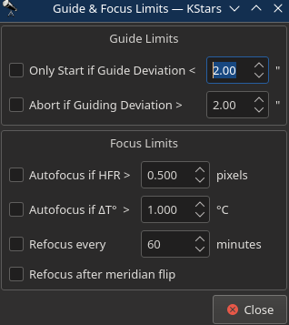
Guide Limits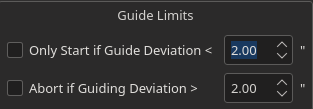
- Only Start if Guide Deviation: Do not resume capture until guide deviation in arcsecs drops below this value. During focus and dithering, guiding deviation may increase slightly before it is stablized back to normal values. This option ensures that capture resumes after focus or dithering only if the deviations are less than the specified value in arcsecs.
- Abort If Guiding Deviation: If checked, it enforces a limit of maximum allowable guiding deviation for the exposure, if autoguiding is used. If the guiding deviation exceeds this limit in arcseconds, it aborts the exposure sequence. It will automatically resume the exposure sequence again once the guiding deviation goes below this limit.
Focus Limits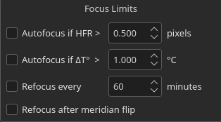
- Autofocus if HFR exceeds a value: If autofocus is enabled in the focus module and at least one autofocus operation was completed successfully, you can set the maximum acceptable HFR value. If this option is enabled then between consecutive exposures, the HFR value is recalculated, and if found to exceed the maximum acceptable HFR value, then an autofocus operation is automatically triggered. If the autofocus operation is completed successfully, the sequence queue resumes, otherwise the job is aborted.
- Autofocus if change in temperature exceeds a value: If autofocus is enabled in the focus module and at least one autofocus operation was completed successfully, you can set the maximum acceptable change in temperature value. If this option is enabled then between consecutive exposures, the change in temperature value is recalculated, and if found to exceed the maximum acceptable change in temperature value, then an autofocus operation is automatically triggered. If the autofocus operation is completed successfully, the sequence queue resumes, otherwise the job is aborted.
- Refocus Every: Run autofocus procedure every X minutes. This runs regardless of current HFR value.
Sequence Queue
Sequence Queue is the primary hub of the Ekos Capture Module. This is where you plan and execute jobs using the sequence queue built-in powerful editor. To add a job, simply select all the parameters from the capture and file settings as indicated above. Once you selected your desired parameters, click on the add button ![]() in the sequence queue to add it to the queue. Grouped parameters are called a Job in Ekos.
in the sequence queue to add it to the queue. Grouped parameters are called a Job in Ekos.
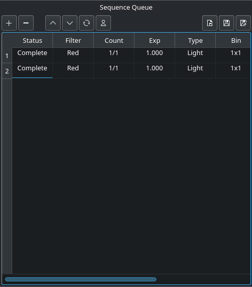 You can add as many jobs as desired. While it is not strictly necessary, it is prefereable to add the dark and flat jobs after the light frames. Once you are done adding jobs, simply click Start Sequence
 ![]() to begin executing the jobs. A job state changes from Idle to In Progress and finally to Complete once it is done. The Sequence Queue automatically starts the next job. If a job is aborted, it may be resumed again. To pause a sequence, click the pause button
to begin executing the jobs. A job state changes from Idle to In Progress and finally to Complete once it is done. The Sequence Queue automatically starts the next job. If a job is aborted, it may be resumed again. To pause a sequence, click the pause button ![]() and the sequence will be stopped after the current capture is complete. To reset the status of all the jobs, simply click the reset button
and the sequence will be stopped after the current capture is complete. To reset the status of all the jobs, simply click the reset button ![]() . Please beware that all image progress counts are reset as well. To preview an image in KStars FITS Viewer, click the Preview button.
. Please beware that all image progress counts are reset as well. To preview an image in KStars FITS Viewer, click the Preview button.
Sequence queues can be saved by as an XML file with extension .esq (Ekos Sequence Queue) by clicking the save capture sequence button ![]() . To load a sequence queue, click the open document button
. To load a sequence queue, click the open document button ![]() . Please note that it will replace any current sequence queues in Ekos.
. Please note that it will replace any current sequence queues in Ekos.
Job Progress: Ekos is designed to execute and resume the sequence over multiple nights if required. Therefore, if Remember Job Progress option is enabled in Ekos Options, Ekos shall scan the file system to count how many images are already completed and will resume the sequence from where it was left off. If this default behavior is not desired, simply turn off Remember Job Progress under options.
To edit a job, double click it. You will notice the add button ![]() now changed to check mark button
now changed to check mark button ![]() . Make your changes on the left hand side of the CCD module and once done, click on the check mark button. To cancel a job edit, click any where empty within the sequence queue table.
. Make your changes on the left hand side of the CCD module and once done, click on the check mark button. To cancel a job edit, click any where empty within the sequence queue table.
To capture a preview image with the settings you have set in the Camera & Filter Wheel Panel, click the Capture a Preview ![]() button. If your camera doesn't support live video feed, click on the Start framing (looping)
button. If your camera doesn't support live video feed, click on the Start framing (looping) ![]() button. If your camera supports live video feed, then you can click the Live Video
button. If your camera supports live video feed, then you can click the Live Video ![]() button to start streaming. The video stream window enables recording and subframing of the video stream. For more information, check the video below:
button to start streaming. The video stream window enables recording and subframing of the video stream. For more information, check the video below:
Live Video
The Live Video window allows live streaming of your camera in order to check if your camera is working fine. You can also record a video, change FPS and zoom in.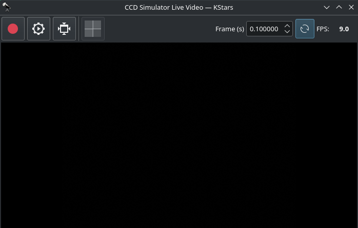
- Start Recording
 : Starts recording everything in the live video frame. Governed by the record options (Until stopped, duration, or frames).
Please note that while recording, the streaming frame rate will drop to increase the efficiency of the video recording process.
- Stop Recording
 : Stops recording and saves a video file.
 - Recording options : Opens the recording options dialog where you can set the following options.
- File name: Set SER video file name. Record files may contain some patterns to make them dynamic:
- _D_ for the date in YYYY-MM-DD.
- _H_ for time in HH:MM:SS.
- _T_ for ISO8601 time stamp.
- _F_ for filter name, if any.
- Directory: Set SER video remote directory name. If INDI server is running locally, then a local directory can be selected. However, if you are
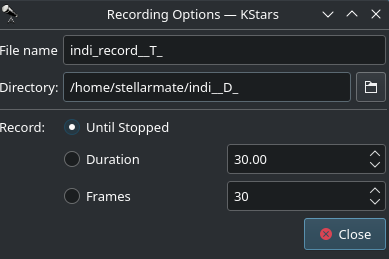 connected to a remote INDI server, then the directory must be a valid directory on the remote file system where it is saved. Record directories may contain some patterns to make them dynamic:
- _D_ for the date in YYYY-MM-DD.
- _H_ for time in HH:MM:SS.
- _T_ for ISO8601 time stamp.
- _F_ for filter name, if any.
- Record:
- Until Stopped: Record stream until manually stopped.
- Duration: Record stream for specified duration in seconds.
- Frames: Record stream until this many frames are captured.
- File name: Set SER video file name. Record files may contain some patterns to make them dynamic:
If Ekos is connected to remote device (eg. StellarMate), please specify the remote directory (eg. /home/stellarmate/Pictures) instead of a local directory. Specifying a local directory could result in errors (as that directory might not exist in the remote device).
- Zooming in: You can zoom in to different parts of your live video frame by clicking and holding, then dragging to another position to create a blue selection, when you release the mouse, the frame will be zoomed in to the selected area.
- Reset frame
 : Unzooms and resets the frame back to default.
 - Toggle debayer
 : Turns on or off Debayering, which is a demosaicing algorithm, it is a digital image process used to reconstruct a full color image from the incomplete color samples output from an image sensor overlaid with a color filter array. It is also known as CFA interpolation or color reconstruction.
 - Frame (s): Specifies the amount of frames per second for the video stream. Click on Apply FPS and restart stream
 when you set a new value for this field.
 - Apply FPS and restart stream : Applies the FPS set in the Frame (s) field and restarts the stream with the new FPS setting.
- FPS: Displays the average FPS of the live video being streamed.
Filter Settings
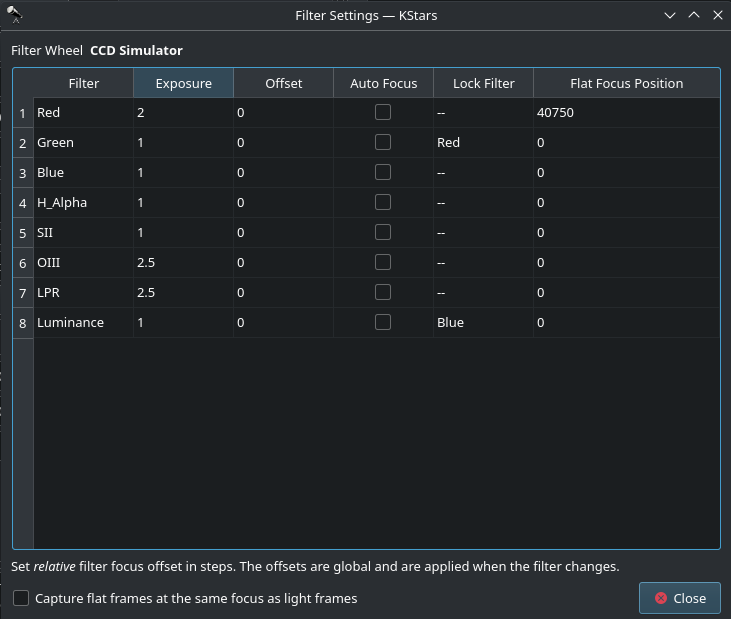 Click the filter icon
 ![]() next to the filter wheel selection box to open the filter settings dialog. If you are using filters that are not parafocal with each other and require a specific amount of focus offsets in order to get them into proper then set all the relative focus offsets in the dialog.
next to the filter wheel selection box to open the filter settings dialog. If you are using filters that are not parafocal with each other and require a specific amount of focus offsets in order to get them into proper then set all the relative focus offsets in the dialog.
Configure settings for each filter individually:
- Filter: Filter Name
- Exposure: Set exposure time used when performing focus under this filter. By default, it is set to 1 seconds.
- Offset: Set relative offsets. Ekos will command a focus offset change if there is a difference between the current and target filter offsets. For example, given the values in the example image to the right, if the curernt filter is set to Red and next filter is Green, then Ekos shall command the focuser to Focus In by +300 ticks. Relative positive focus offsets denote Focus Out while negative values denote Focus In.
- AutoFocus: Check this option to initial AutoFocus process whenever the filter is changed to this filter.
- Lock Filter: Set which filter should be set and locked when performing autofocus for this filter.
- Flat Focus Position: this value is set automatically once you finish autofocus for some filter. If the sequence queue contains flat images, then Ekos would first move the focuser to the filter absolute focus position before capturing the flat images. This to ensure both your light and flat frames are exactly captured using the same per-filter offset.
Let's take an example. Suppose the capture sequence is running and the current filter is Green, so the relative already offset is set to +300. The next image in the sequence uses Hydrogen Alpha (H_Alpha) so before Ekos captures the next frame, the following actions take place:
- Since Lumonisity is specified as the locked filter and auto-focus is checked, the filter is changed to Lumonosity
- A focus offset is -300 is applied since the prior filter Green was moved +300 previously.
- Auto Focus process is initiated.
- Once Auto Focus is complete, the filter is changed to H_Alpha.
- A focus offset of -1200 is applied.
- Capture sequence is resumed.
FITS Viewer
Captured images are displayed in KStars FITS Viewer tool, and also in the summary screen.
Tools
- Dark Library: Create and Manage Dark Frames for your cameras. The dark frames are to be used in the Focus, Align, and Guide modules in order to reduce the noise in images to improve the performance of star detection algorithms. This is not used to post-process your captured images, it is only used internally to increase the reliability of the various Ekos modules.
- Scripts Manager: Specify custom scripts to be executed at various stages of the capture process. A script must be an executable file that returns zero on success. It can be written in any scripting language like Python or Bash.
Rotator Settings
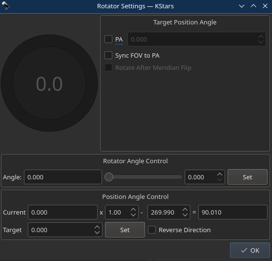
Field Rotators are supported in INDI & Ekos. The rotator angle is the raw angle reported by the rotator and is not necessary the Position Angle. A Position Angle of zero indicates that the frame top (indicated by small arrow) is pointing directly at the pole. The position angle is expressed as E of N (East of North), so 90 degress PA indicates the the frame top points 90 degrees away (counter-clockwise) from the pole. Check examples for various PAs.
To calibrate the Position Angle (PA), capture and solve an image in the Ekos Align module. An offset and a multipler is applied to the raw angle to produce the position angle. The Ekos Rotator dialog permits direct control of the raw angle and also the PA. The offset and multiplier can be changed manually to synchronize the rotator's raw angle with the actual PA. Check Sync FOV to PA to rotate the current Field of View (FOV) indicator on the Sky Map with the PA value as you change it in the dialog.
Reverse Direction: Reverses the direction of rotator to opposite directions.
Each capture job may be assigned different rotator angles, but be aware that this would cause guiding to abort as it would lose track of the guide star when rotating. Therefore, for most sequences, the rotator angle is kept the same for all capture jobs.
Calibration Frames
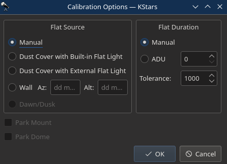 For Flat Field frames, you can set calibration options in order to automate the process. The calibration options are designed to facilitate automatic unattended flat field frame capture. It can also be used for dark and bias frames if desired. If your camera is equipped with a mechanical shutter, then it is not necessary to set calibration settings unless you want to close the dust cover to ensure no light at all passes through the optical tube. For flat fields, you must specify the flat field light source, and then specify the duration of the flat field frame. The duration can be either manual, or based on ADU calculations.
- Flat Field Source
- Manual: The flat light source is manual.
- Dust Cover with Built-In Flat Light: If using a dust cover with built-in light source (e.g. FlipFlat). For dark and bias frames, close the dust cap before proceeding. For flat frames, close the dust cap and turn on the light source.
- Dust Cover with External Flat Light: If using a dust cover with external flat light source. For dark and bias frames, close the dust cap before proceeding. For flat frames, open the dust cap and turn on the light source. The external flat light source location is presumed to be the parking location.
- Wall: Light source is a panel on the observatory wall. Specify the Azimuth and Altitude coordinates of the panel and the mount shall slew there before capturing the flat field frames. If the light panel is controllable from INDI, Ekos shall turn it on/off as required.
- Dawn/Dusk: Currently unsupported.
- Flat Field Duration
- Manual: Duration is as specified in the Sequence Queue.
- ADU: Duration is variable until specified ADU is met.
Before the calibration capture process is started, you can request Ekos to park the mount and/or dome. Depending on your flat source selection above, Ekos will use the appropiate flat light source before starting flat frames capture. If ADU is specified, Ekos begins by capturing a couple of preview images to establish the curve required to achieve the desired ADU count. Once an appropiate value is calculed, another capture is taken and ADU is recounted until a satisfactory value is achived.
Dark Flats
When you add flat frame jobs where the Flat Field duration is specificed as an ADU value, Ekos shall take multiple exposures until the flat frame's average ADU matches the desired value. You can add corresponding Dark Flats to be captured after Flat frames are completed so that it matches the same duraiton of the captured flat frames. After adding the flat frames, simply click the Generate Dark Flats button ![]() to create sequence jobs for the dark flats. If the sequence queue contained multiple flat frames, each for a specific filter, then the dark flats would be generated for each filter. Please ensure to run the dark flats in the same Ekos session as the flat frames. If Ekos is restarted before Dark Flats are captured, then the information on the dynamic exposure times per flat frame is lost.
to create sequence jobs for the dark flats. If the sequence queue contained multiple flat frames, each for a specific filter, then the dark flats would be generated for each filter. Please ensure to run the dark flats in the same Ekos session as the flat frames. If Ekos is restarted before Dark Flats are captured, then the information on the dynamic exposure times per flat frame is lost.
Dark Library
The Dark Library is a collection of dark frames captured from your cameras under different settings. There are basically five primary types of frames:
- Light Frame: This is the regular image captured by your sensor. It is called light because it captures the incoming light received at the sensor.
- Dark Frame: A frame captured with the same settings as the light frame (same temperature, exposure time, and binning) but with the shutter closed so that no photons reach the sensor. This is used to record the electronic noise generated by the sensor without any incident photons. It is used to remove noise from the Light Frame by means of subtraction since the Light Frame includes signal from both the incoming photons and electronic noise generated by the sensor.
- Bias: A very short exposure with the shutter closed.
- Flat: A frame captured with the same settings as the light frame (same temperature, exposure time, and binning) but subjected to an illuminated flat field source (such as an LED panel). This is used to correct for optical aberrations in the imaging train including dust motes.
- Dark Flats: Special type of dark frames captured at the same exposure of flat frames. This is used to calibrate the flat frames.
Generating a dark library for your equipment profile is highly recommended. When capturing frames in focus, guide, and align modules, the system searches the dark library for suitable dark frames. If a suitable match is found, the light frame is calibrated and this can greatly enhance the performance and accuracy of all Ekos modules.
Note: Dark Library is not used to calibrate your sequence images, it is only used to calibrate the Align, Focus, and Guide module frames.
Dark frame calibration can be applied using two methods:
- Dark Subtraction: The dark frame is simply subtracted from the light frame. This is the recommended method when using a cooled camera.
- Defect Maps: For uncooled cameras (e.g. Guide), dark frames may not be suitable for removing the hot and pixels present in the image. An alternative method generates a map of bad pixels that should be treated in the light frame. You can adjust the Hot and Cold pixels sliders to include or exclude pixels. It’s recommended not to include more than 5,000 pixels as it can become computationally expensive to correct this many pixels in guide images. Ekos corrects each defective pixel by using calculating the median value from surrounding pixels.
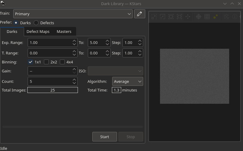
Preset: Select which capture preset to use. The camera name, gain, and offset are used from the preset while the exposure and temperature settings (if supported) are configured in the Create Dark Library window.
Prefer: Select which dark calibration method to utilize for the selected preset. Both methods are used to remove noise from the light frame:
- Dark: Remove noise by means of dark frame subtraction.
- Defect Maps: Remove noise by means of defect map substitution.
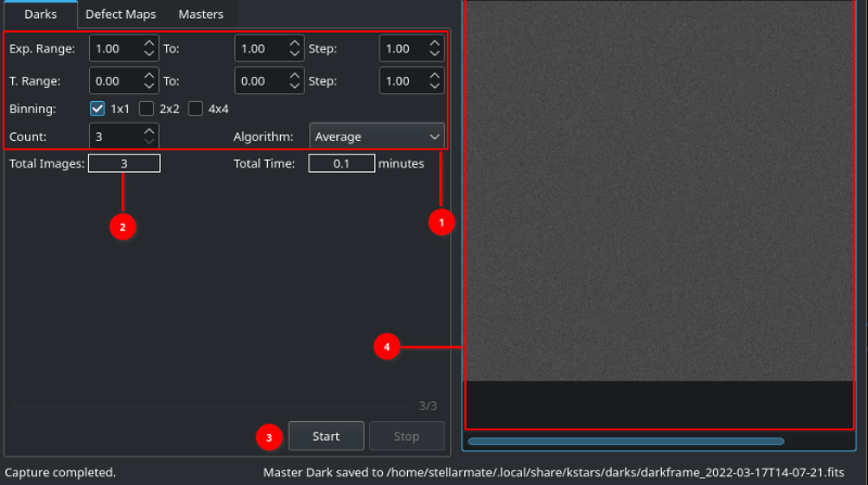 Create Darks: Create a master dark frame by capturing and averaging a number of individual dark frames.
- Select the range of exposures, binning, and temperatures (if applicable) required.
- Each time you change a selection, the Total Frames count is updated to reflect the required frames.
- When ready, tap the Play button to start the process.
- Captured Dark Image will be updated in FITS Viewer
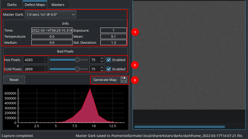 Create Defect Map: After creating a master dark, you can create a defect map for your camera. Usually, defect maps are used when dark frame subtraction does not improve the quality of the calibration result. This is especially evident when using uncooled guide cameras that can exhibit hot pixels that are hard to treat with classical dark frame subtraction methods.
- Select the master dark frame and it will load the information of a specific image.
- Then adjust Hot and Cold pixel sliders to include or exclude pixels.
- Click Generate Map to inspect the results and once satisfied tap the save button to store the defect map for future use.
View Masters: Inspect master frames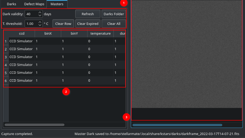
1. Validate & Clear: Validity of the Image can be set, Specific Row or Expired Master Frames can be deleted. Refresh to load new images if not updated. Clear all will delete all the images for the Specifc Camera.
2. Master Files: All Images are loaded here.
3. FITS Viewer: Selected Image is loaded here.
Video Tutorials
Capture
Filter Wheels